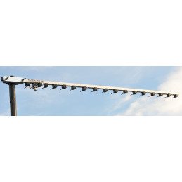
** I have one of these antennas myself at my remote summer house by the North Sea. The Heavy Duty versions of Goran's antennas are completely second to none and can sit for many years without blowing to pieces. This is due to the oversized boom and the stiff radials and good element holders.
Aluminum can corrode in salt water and in wind close to the sea. I treat my antennas with CorrosionX spray, a very common rust protection on spray/film, everywhere where steel meets aluminum. (possibly spray the entire boom before assembling the antenna).
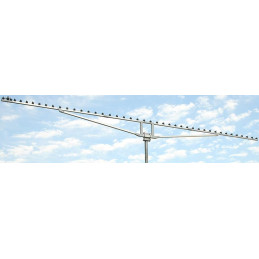
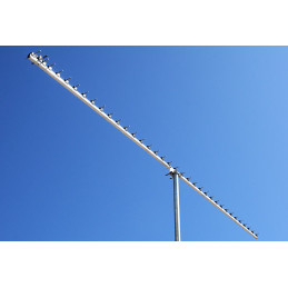
The 56-element 1296 MHz Heavy Duty Antenna has reinforced construction that helps keep the antenna always strait. 23cm56AUTHD plain view of the antenna:

What does 23cm56AUTHD mean?
23cm – Frequency range from 1290 to 1310 MHz with low SWR
56 – Elements
A – Max Package size <120 cm. Can fit in an airplane as “baggage”
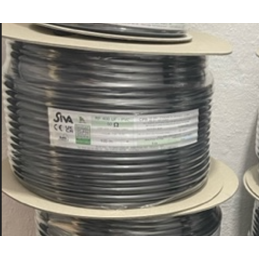
UT – UT141 or similar Teflon cable
HD – Heavy Duty construction antenna
Easy to put on the top of any mast. You do not need to worry about whether it is fiberglass or not since antenna elements will be higher. Any pipe from 40 to 70 mm will be good.
The 23cm56AUTHD old sign PA1296-56-4.7AUTHD antenna has exceptional gain for its size with 22.3 dBi and an immense front-to-back ratio of 35 dB.

23cm56AUTHD Order versions:
1. Default 1290 – 1310 MHz designed for terrestrial and EME communication.
2. Wideband 1240 – 1310 MHz. Covers a full 23cm band. Some of the more common modes include voice, data, EME (moonbounce), as well as ATV.
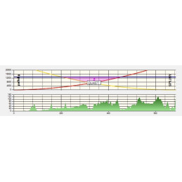
Measurement of 23cm Heavy Duty Antenna with 56 Elements 23cm56AUTHD

Electrical Specifications of 23cm56AUTHD
Frequency Range: 1290 – 1310 MHz (or 1240 – 1310 MHz by request)
Free Space Forward Gain: 22.3 dBi
Front to Back Ratio: 35 dB
-3 dB Horizontal Beam-width: 14.9°
Polarization: Horizontal
Nominal Input Impedance: 50 Ohms
SWR Across Entire Band: < 1.2
Maximum Power Input: 100 W
Matching Method: Voltage balun. UT141 or similar Teflon cable
Connector: “N”

Mechanical Specifications of 23cm56AUTHD
Number of Elements: 56
Element Diameter: 4 mm Aluminum rod
Dipole Diameter: 3 mm Copper
Longest Element: 120 mm
Element Mounting Position: Above the boom
Balun and Connectors: Included
Boom Length: 4.7 m
Boom Size: 20×20 mm with 20 x 30 mm heavy-duty support
The number of Boom Pieces: 4
Mounting Mast Diameter: 40 – 70 mm 1-11/16″ – 2-3/4″ OD
Clamp: M8 Stainless Steel
Survival Wind Speed: 150 km/h
Net Weight: 4.8 kg
Gross Weight: 6 kg
Transportation Length: 1.2 m
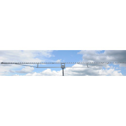
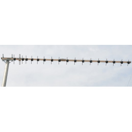
View from behind:

The antenna is 4.7 meters long and has a similar design to our shorter and longer HD versions.
– 43 Elements on the 3.6-meter boom. Heavy duty antenna PA1296-43-3.6AUTHD
– 70 Elements on the 6-meter boom. Heavy duty antenna PA1296-70-6AUTHD.
The 23cm56AUTHD has a similar construction as our PA1296-70-6AUT antenna. A YouTube video about construction and how to assemble is here.
View all our 23 cm antennas here.
More about Antennas-Amplifiers
Antennas-Amplifiers Product Benefits. A Major advance in Amateur Radio antenna design.
All antennas have been calculated using state-of-the-art full 3D Electromagnetic Simulation Software including the influence of the boom, bracket, baluns, and connectors. The performance of antennas designed using these techniques is exceptional, far better than antennas designed using “wire” programs.
Before dispatch, we assemble every antenna and test antenna characteristics. That means you may expect exceptionally good electrical and mechanical characteristics including low SWR across the designed range immediately after assembling.
No need to move dipole, cut or tune any element to get perfect SWR on the intended frequency range. Everything is pre-tuned.
That lead also to another very important detail. When assemble and test each antenna is complete with all washers, nuts, bolts guy rope supports, etc.
When packing all parts are already on the antenna without the possibility of “forgetting” important parts to put in the box. So you will always receive the complete antenna that we tested just before dispatching.
- Designs that work well in all weather conditions
- Low SWR and superior G/T, F/B, and F/S ratios across the entire bands
- Excellent mechanical properties
- High durability, built without compromise
Why all the above is very important? Why we do not use free wire programs like EZNEC (Pro), 4NEC2, MMANA-GAL, or AO? Like all other producers or simulators do?
EZNEC, 4nec2, or AO producers or simulators puts on the web pages excellent “simulated” antenna patterns produced by wire programs. Looks good on a computer screen. But what about reality?
Elements are not infinitesimally thin.
Boom size is not 0 (zero) mm.
Boom corrections programs exist. But what about accuracy?
Electrical terminals from balun coaxial cable to dipole are probably at least 10 mm long which is not “simulated” 0 (zero) mm. It will lead to worsening SWR or when tuned to good SWR to sharp antenna resonance.
Real antennas are not in free space. They are surrounded by metal parts not calculated in any form by wire programs.
Errors made by programs like EZNEC (Pro), 4NEC2, MMANA-GAL, AO, etc. only for the above examples are unacceptable these days. They will lead to wrong antenna gain and specially F/B. At least 5-15 dB lower than predicted. That means if the antenna is “calculated” for F/B 30 dB it could be anywhere between 15dB to 25dB. Unfortunately, that also means the antenna will have much worse G/T which will lead to bad contest results and poor EME reception.
This has nothing to do with the obtained SWR of 1: 1 on an antenna. SWR 1:1 is not related in any circumstances with antenna gain, F/B, or G/T.